Installation
Before pairing the app, the device needs to be installed: mounted, wired, and the sensor placed. This guide covers the essentials; for specific cases also check the installation FAQ.
The controller runs on direct line voltage (110 V or 220 V). We strongly recommend that the electrical work be done by a qualified electrician, in accordance with local electrical codes. Before touching any wire, cut power to the circuit and confirm with a tester that it is dead.
Parts of the device
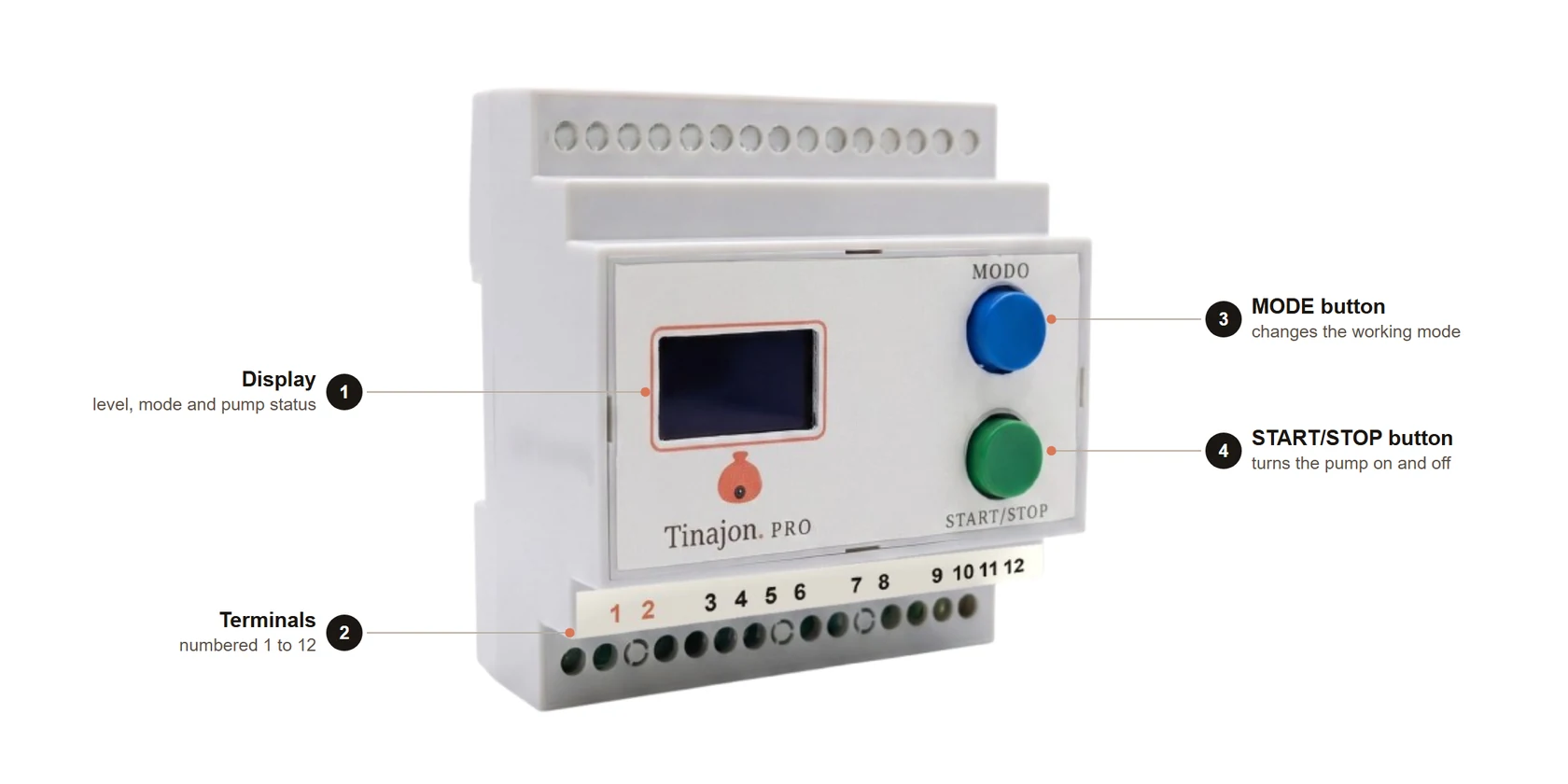
| No. | Part | What it's for |
|---|---|---|
| 1 | Display | Shows the tank level, the working mode, and whether the pump is running. |
| 2 | Terminals | The device's 12 numbered connections. This is what you wire in this guide. |
| 3 | MODE button | Switches between automatic, semi-automatic and manual. |
| 4 | START/STOP button | Turns the pump on and off by hand. |
What you need
- The Tinajon Pro controller.
- The ultrasonic sensor and its cable.
- A dry-contact float switch for the cistern — optional, see below.
- A contactor, only if your pump draws more than 16 A — see "Wire the pump".
- An SCT-013 current clamp — only on the model with power metering, and optional: see Power metering.
- Access to the electrical panel, or a powered point near the pump.
- Basic electrician's tools (screwdriver, wire strippers, voltage tester).
Mount the controller
The controller is DIN rail format. You can mount it inside an existing electrical panel, or fix a piece of DIN rail to any surface near the pump and clip it on there.
- Pick a dry, ventilated spot close to the pump and the electrical panel.
- Fix the DIN rail to the surface (or use one already in your panel).
- Clip the controller onto the rail — no extra screws needed.
The terminals
Every connection is in a single row —part 2 in the figure—, numbered 1 to 12 on the device label. The strip has 15 holes: the three without a number are unused, and act as spacing between groups.
| No. | What it is | Connects to |
|---|---|---|
| 1 | L — line | Controller power (110 V or 220 V) |
| 2 | N — neutral | Controller power |
| 3 | NO — normally open | Output to the pump, or to the contactor coil |
| 4 | NO — same contact as 3 | Output to the pump (second wire) |
| 5 | COM — common | Output to the pump, or to the contactor |
| 6 | COM — same contact as 5 | Output to the pump (second wire) |
| 7 | Float switch signal | Cistern float switch (optional, no polarity) |
| 8 | Float switch GND | Cistern float switch |
| 9 | 5 V | Ultrasonic sensor — orange wire |
| 10 | TRIG | Ultrasonic sensor — green wire |
| 11 | ECHO | Ultrasonic sensor — blue wire |
| 12 | GND | Ultrasonic sensor — brown wire |
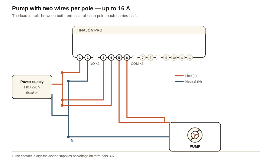
Pairs 3/4 and 5/6 are the same relay contact, repeated so two wires fit without splicing. If you split the load across two wires per pole — one in 3 and one in 4, one in 5 and one in 6 — each terminal carries half and the set takes up to16 A. With a single wire per pole, the limit is 8 A.
System overview
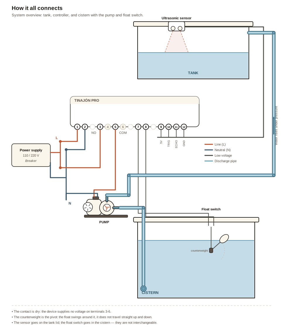
Before going terminal by terminal, here's the whole system: the sensor on the tank lid, the controller in the middle, and the cistern with the pump and the float switch.
Wire the power — terminals 1 and 2
- With the power off, connect line to terminal 1 (L) and neutral to terminal 2 (N).
- The device accepts 110 V or 220 V and adapts on its own: nothing to configure, no switch to flip.
- Tighten firmly and give each wire a gentle pull to confirm it is held.
Wire the pump — terminals 3 to 6
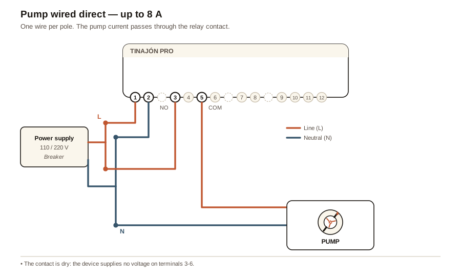
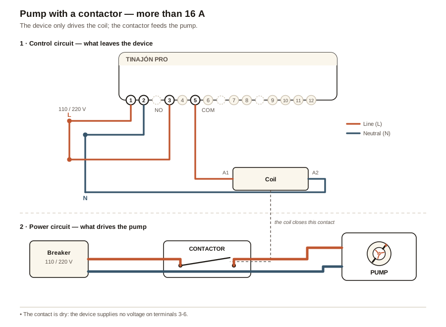
The controller's output is a dry contact: the relay only opens and closes, it does not supply any voltage of its own. The pump current comes from your own installation, passing through the contact.
There are three ways to wire it, and which one applies depends on your pump:
| Pump current | How to wire it |
|---|---|
| Up to 8 A (≈ 900 W at 110 V · ≈ 1750 W at 220 V) | Direct, one wire per pole: line in on 3, out on 5 to the pump. |
| 8 to 16 A (≈ 1750 W at 110 V · ≈ 3500 W at 220 V) | Direct, two wires per pole: one on 3 and one on 4, one on 5 and one on 6. Each terminal carries half. |
| More than 16 A | With a contactor: terminals 3-6 drive the contactor coil, and the contactor switches the pump. |
With one wire per pole, the limit comes from the terminal block, not the relay. The thinnest link is the screw terminal, rated 10 A by UL and CSA, and 8 A leaves margin for the pump's inrush. With two wires per pole each terminal carries half, and at 16 A each one is still at those 8 A: the board and the relay take more, so the terminal block is still the limit. Go by the nameplate current of your pump, not its horsepower: if you can't find it or you're unsure, use a contactor — they're cheap, and it is always the safe choice.
With no power to the device the contact sits open, so the pump cannot start on its own when the power comes back without the controller taking over first.
Wire the float switch — terminals 7 and 8 (optional)
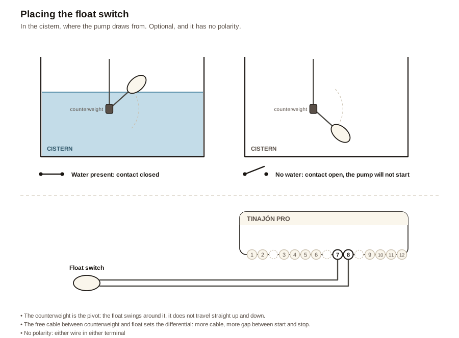
The float switch goes in the cistern (the tank the pump draws from) and keeps the device from running dry when that source is empty. It is a two-wire dry contact: there is no polarity, either wire goes in either terminal. Three-wire float switches (common, normally open and normally closed) work too: use the common and one of the other two, and insulate the spare one.
If your water source never runs empty — mains water straight from the street, for example — you can skip it and leave terminals 7 and 8 unused. The cistern sensor ships turned off, so there's nothing to change.
How to hang it
The float does not travel straight up and down: it swings. The counterweight on the cable is clamped at whatever height you choose and acts as the pivot — like an elbow — while the float swings around it like a hand. The contact switches once it passes about 45°.
- Hang the cable from the cistern lid and clamp the counterweight at the height where the device should consider the cistern empty.
- Let the counterweight hang free, clear of the wall and the bottom.
- The free cable between counterweight and float sets the differential: the more cable you leave, the more the level has to change before it switches.
Turn it on and check which way it works
Some float switches close the contact when there's water and others close it when the cistern empties. Instead of guessing, you tell the device and check it by hand:
- In the app, Settings → Pump and sensor, turn on "Cistern sensor".
- Below it, under "When there's water, the float contact…", leave "Closes" — the usual case — and save.
- Lift the float by hand: the app should say the cistern has water. Let it hang: it should say empty. If it's the other way round, pick "Opens", save and try again.
With "Closes", a cut cable reads as "cistern empty" and the pump won't start: it fails safe. With "Opens" it's the other way round: a cut cable reads exactly like "there is water" and the dry-run protection silently stops working. In automaticand semi-automatic modes the 100 % cutoff and the flow watchdog still cover you; in plain manual mode neither one does. So if your float switch allows it — three-wire ones always do — use the pair that closes with water. Either way, check the float switch cable as part of your annual maintenance.
Install the sensor — terminals 9 to 12
The ultrasonic sensor measures the distance to the water from above, so it goes on the lid or top of the tank, pointing straight down.
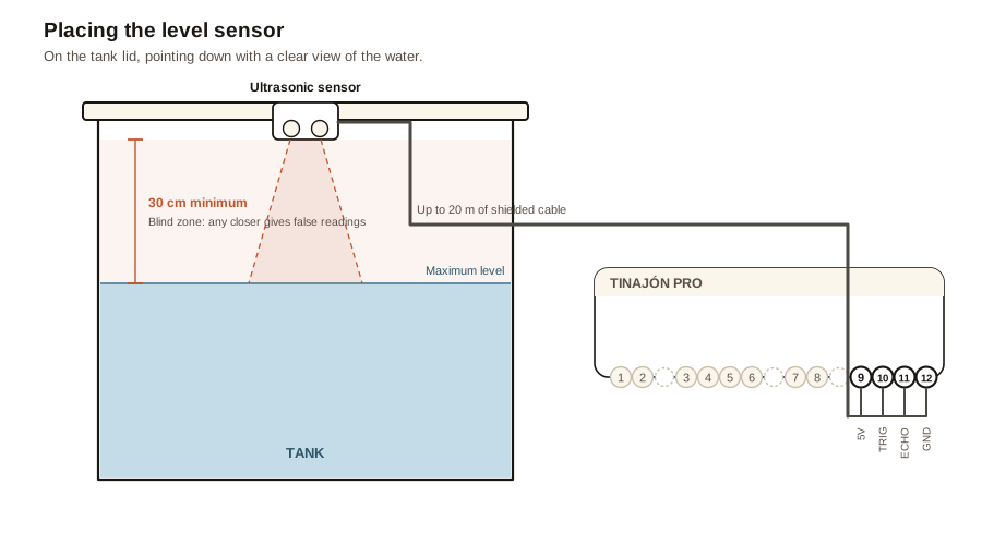
- Fix the sensor to the tank lid with a clear line of sight to the water — nothing in between the sensor and the surface.
- Leave at least 30 cm between the sensor and the maximum water level. Any closer and the sensor enters its blind zone and returns false readings.
- Run the cable to the controller. You can use up to 20 metres without losing accuracy — use shielded cable and keep it away from high-voltage wiring.
- At the controller, connect the four wires to terminals 9 (5 V, orange), 10 (TRIG, green), 11 (ECHO, blue) and 12 (GND, brown).
- At the tank, screw them into the sensor's adapter board in the same order: +5V and TRIG in one terminal block, ECHO and GND in the other. The names are printed next to each terminal.
Before applying power, check that each color reaches the same name at both ends: orange to 9 and to +5V, brown to 12 and toGND. Swapping 5 V and GND can damage the sensor.
Power it up
Restore power. The OLED screen should light up within a few seconds and show the device status — that confirms it started correctly. If the screen stays dark, cut the power and check terminals 1 and 2 before going on.
If "SIN SENSOR" (no sensor) blinks instead of the level, the device isn't getting a reading: cut the power and check terminals 9 to 12. With the sensor properly connected you'll see a percentage right away — approximate until you calibrate it in the app, in the next chapter.
Next step: with the device installed and powered up, continue with Getting started to pair it with the app.